We know that the OSI model of a networking system includes seven layers like physical, data link, network, transport, session, presentation, and applications where each layer has some protocols. So, the first two layers in the OSI model like the physical layer and data link layer have a very popular set of Ethernet protocols. Ethernet protocol is available around us in various forms but the present Ethernet can be defined through the IEEE 802.3 standard. So, This article discusses an overview of Ethernet protocol basics, types and it’s working.
Ethernet protocol definition: The most popular and oldest LAN technology is Ethernet Protocol, so it is more frequently used in LAN environments which is used in almost all networks like offices, homes, public places, enterprises, and universities. Ethernet has gained huge popularity because of its maximum rates over longer distances using optical media. The Ethernet protocol uses a star topology or linear bus which is the foundation of the IEEE 802.3 standard. The main reason to use Ethernet widely is, simple to understand, maintain, implement, provides flexibility, and permits less cost network implementation.
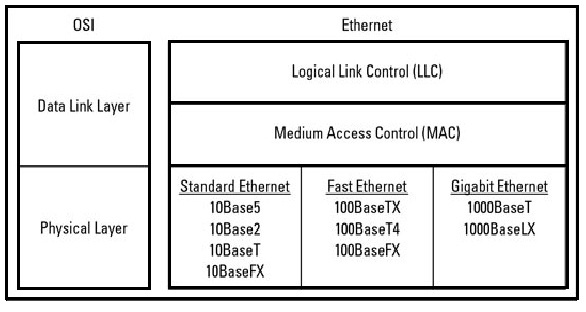
In the OSI network model, Ethernet protocol operates at the first two layers like the Physical & the Data Link layers but, Ethernet separates the Data Link layer into two different layers called the Logical Link Control layer & the Medium Access Control layer. The physical layer in the network mainly focuses on the elements of hardware like repeaters, cables & network interface cards (NIC). For instance, an Ethernet network like 100BaseTX or 10BaseT indicates the cables type that can be used, the length of cables, and the optimal topology. The data link layer in the network system mainly addresses the way that data packets are transmitted from one type of node to another. Ethernet uses an access method called CSMA/CD (Carrier Sense Multiple Access/Collision Detection). This is a system where every computer listens to the cable before transmitting anything throughout the network.
Ethernet protocol mainly works in the first two layers in the OSI network model like data-link & physical. Ethernet at the first layer uses signals, bitstreams that move on the media, physical components that situate signals on media & different topologies. Ethernet plays a key role at Layer 1 in the communication that occurs between different devices, however, every function of this has some limitations. The sub-layers of Data Link give significantly to technological compatibility & computer communications. The MAC sublayer is anxious through the physical components that will be utilized to converse the information & arrange the data for communication over the media. The Logical Link Control sublayer will stay independent of the physical equipment that will be utilized for the process of communication.
Ethernet protocol simply divides the Data Link layer functions into two separate sublayers like the Logical Link Control sublayer & the Media Access Control sublayer. The functions of the Data Link layer in the OSI model are allocated to both the sublayers like LLC & MAC. For Ethernet protocol, the IEEE 802.2 standard simply explains the functions of the LLC sublayer & the 802.3 standard explains the functions of MAC & the Physical layer. The Logical Link Control (LLC) handles the communication between the upper layers & the lower layers. The LLC layer uses the data of network protocol like IPv4 packet & adds control data to help in delivering the packet toward the destination node. The second layer (Layer 2) interacts through the higher layers using LLC which can be implemented within software & its implementation is independent of the physical devices. In a computer system, the logical link control can be considered the driver software of the NIC or Network Interface Card. So, the driver software of NIC is a program that directly communicates through the hardware on the network interface card to transmit the data in between the two layers of MAC & Media.
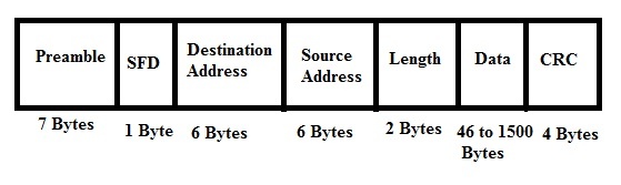
Generally, the structure of the Ethernet frame is defined within the IEEE 802.3 standard. But there are numerous optional frame formats are being employed for Ethernet to expand the capacity of the protocol. The Early frame versions were very slow but the latest Ethernet versions operate at 10 Gigabits/sec. So this is the very fastest Ethernet version. The frame structure at the data link layer in the OSI model is almost the same for all Ethernet speeds. The structure of the frame simply adds headers & trailers in the region of the Layer 3 PDU (Protocol Data Unit) to summarize the message. The frame structure of Ethernet is shown below and it begins with the Preamble that functions at the physical layer Ethernet header includes both Source & Destination MAC address, after which the frame’s payload is present. The end field is Cyclical Redundancy Checking, used to notice the error. The following diagram shows the structure of the frame & fields.
The first pattern of the Ethernet Protocol frame is 7-Bytes of Preamble where alternative 0’s and 1’s in this frame indicate the beginning of the frame & permit the sender & receiver to set up bit-level synchronization. At first, a Preamble in the above frame was introduced to permit for the few bits loss because of signal delays. However, present high-speed-based Ethernet doesn’t require Preamble for protecting the frame bits. Preamble specifies the receiver that frame is coming & lets the receiver lock on the data stream before the genuine frame starts.
The start of frame delimiter (SFD) is a 1-Byte field with 10101011 values that indicates that upcoming bits are the beginning of the frame, which is the address of the destination. The start of the frame delimiter is mainly designed to split the pattern of the bit to the preamble & signal the beginning of the frame. Sometimes, the start of frame delimiter is considered as the main part of the preamble, so this is the main reason that Preamble is expressed as 8 Bytes in several places. The SFD gives a warning to stations that this is the final opportunity for synchronization.
The Destination Address Field is a 6-bytes field in the above Ethernet frame. The address within the frame & the device MAC address is compared. If both the addresses are matched, then the device simply allows the frame. This MAC address is a uni-cast, multi-cast, or broadcast.
The source address is a 6-Byte field, including the source machine’s MAC address. Once the address of source is an individual address or Unicast always, then LSB of an initial byte will be always.
This field size is 2-byte long that specifies the entire Ethernet frame length. The length value held by the 16-bit field ranges from 0 to 65534, however, the length cannot be higher than 1500 due to some own Ethernet limitations.
Data field is the location where actual data can be added and it is also called Payload. Here, both the data & IP header will be inserted if IP is used over Ethernet. So, the highest data available may be 1500 Bytes. If the data length is below the minimum length of 46 bytes, then padding zeros can be included to reach the minimum achievable length.
The CRC in the frame is the last pattern with 4 Bytes. This field includes 32-bits of data hash code, which is produced over the Source Address, Destination Address, Length, and Ethernet Protocol’s Data field. If the checksum is calculated through a destination that is not similar to the sent checksum value, then received data can be corrupted. Here, the frame size for IEEE 802.3 Ethernet standard changes from 64 bytes – 1518 bytes with 46 to 1500 bytes of data length.
In the above, the standard Ethernet frame is discussed in detail. Now let’s discuss the extended Ethernet frame using which we can obtain Payload even higher than 1500 Bytes.
An Ethernet standard mainly explains the functions, properties & specific media type implementation. There are different media types available that can provide different transmission speeds on different kinds of implementation. These standards are simply defined through IEEE. The terminology used to express Ethernet standards is transmission type, speed, and cabling type or length.
| Standard | IEEE Documentation/Ethernet Specification | Speed | Cable | Minimum Cable Grade | Maximum Distance |
| 10Base5 | 802.3 | 10Mbs | Coaxial | RG-8 | 500 meter |
| 100BaseT/TX | 802.3u | 100 Mbps | UTP | Cat 5 | 100 meters |
| 10Base2 | 802.3a | 10Mbps | Coaxial | RG-58 | 200 meter |
| 100BaseFX | 802.3u | 100 Mbps | MMF or SMF | N/A | 2 km on MMF & 10 km on SMF |
| 10Base-T | 802.3i | 10 Mbps | UTP | Cat 3 | 100 meters |
| 1000BaseT | 802.3ab | 1000 Mbps | UTP | Cat 5/Cat6 | 100 meters |
| 40 Gigabit Ethernet | 802.3ba | 40 Gbps | MMF, SMF & copper | N/A | 40 km on SMF, 7 meters on copper |
| 100 Gigabit Ethernet | 802.3bj & 802.3bm | 100 Gbps | N/A | MMF, SMF | 100 km |
| 10GBaseT | 802.3an | 100 meters | UTP | Cat 6A | 10 Gbps |
| 10GBaseSR 10GBaseLR 10GBaseER 10GBaseSW 10GBaseLW 10GBaseEW | 802.3ae | 10 Gbps | MMF/SMF | N/A | 82 meters – 40 km |
| 100BaseT4 | 802.3u | 100 Mbps | UTP | Cat 3 | 100 meters |
| 1000BaseCX | 802.3z | 1000 Mbps | Twinax | N/A | 25 meters |
| 1000BaseLX | 802.3z | 1000 Mbps | MMF /SMF | N/A | 550 meters on MMF, 5 km on SMF |
| 1000BaseSX | 802.3z | 1000 Mbps | MMF | N/A | 550 meters |
This protocol analyzer is a software tool mainly used for capturing & analyzing the traffic of data within a network. These analyzers can also build the graphic map of the network and generates alarms once the number of packets increases at a specified level otherwise once it detects particular types of packets within the network.
These protocol analyzers are generally used by developers for capturing & analyzing the data traffic from their applications. The number of functions mainly depends on the complexity of the analyzer. However, all analyzers must be capable to capture & analyze network packets & filtering data. Some of the functions of the protocol analyzer include the following.
An example of a protocol analyzer is HTTP Debugger for Windows that captures all the traffic of the network at a specific level & it can decode the traffic of SSL. Most protocol analyzers decode nearly three hundred various protocols. So when the analyzer presents more information then manual work will be less to do.
The advantages of Ethernet protocol include the following.
The disadvantages of Ethernet protocol include the following.
The applications of Ethernet protocol include the following.
Thus, this is all about an overview of an Ethernet protocol and its working. Ethernet is one type of communication protocol, used to connect computers in a LAN & WAN where both LAN & WAN connects several devices like printers, laptops in buildings, homes, etc. here is a question for you, what are the other different types of internet protocols available?